
When I started Crestron programming in 2010, you had to take two classes. One covered almost the entire Crestron catalog. All I can remember is my eyes glazing over after a couple days of that. We might have built a touchpanel layout, too. The second class actually got into SIMPL programming, but we only covered button presses, feedback, interlocks, and maybe a toggle. It was fairly basic, but it was enough to get started programming Crestron systems.
After passing the exam at the end of class, they told us to go program systems for a year then come back and take the 201 class.
In 201, we covered signal naming, shortcut keys, and dipping our toes into SIMPL+. We got to use a few more symbols during class, dealing mostly with analog and serial data. The instructor also mentioned crosspoints and–probably due to our confused looks–took a detour into discussing them. This might have been the only demo of crosspoints I ever received from Crestron; I don’t remember talking about them in 301 at all.
This post is mostly an explanation about how to use crosspoints, but I added a couple tips towards the end.
Buffers
Everybody understands Buffers, right? Signal comes into the left side, and when the enable join goes high, everything propagates to the right side:
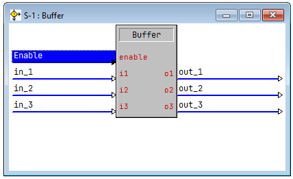
In a traditional programming language, this would be like an IF statement. When enable is high (true), things happening on the left pass to the right. When enable is low (false), everything on the right stays low.

Analog and Serial Buffers work in a similar fashion, but can propagate analog or serial joins. Analog Buffers will immediately propagate values on the left to the right when enable goes high. I think about this as maybe a value is changing frequently, but I only care to sample it at a specific moment. The Analog Buffer will remember the last value and pass it through.
Serial Buffers only pass values through when enable is high and the incoming signal changes. This makes sense if you’re thinking about serial joins because they don’t really have a permanent value (unless they’re tied to a Make String Permanent symbol). I think about these as opening a valve on a pipe and waiting for whatever comes next (signal).
Multiple Touchpanels, Multiple Devices
So if we have buffers, why do we need crosspoints? Crestron has a good illustration in their help file, so I’m just going to put it here:

This shows 4 touchpanels each able to control any of 5 devices. There are 20 connections possible. If we have to buffer digital, analog, and serial signals separately, that’s 60 connections to manage!
Since I only program commercial systems, I tend to use crosspoints for divisible spaces. This way, I can have multiple touchpanels that can either work independently or all track the same.
Control Crosspoints
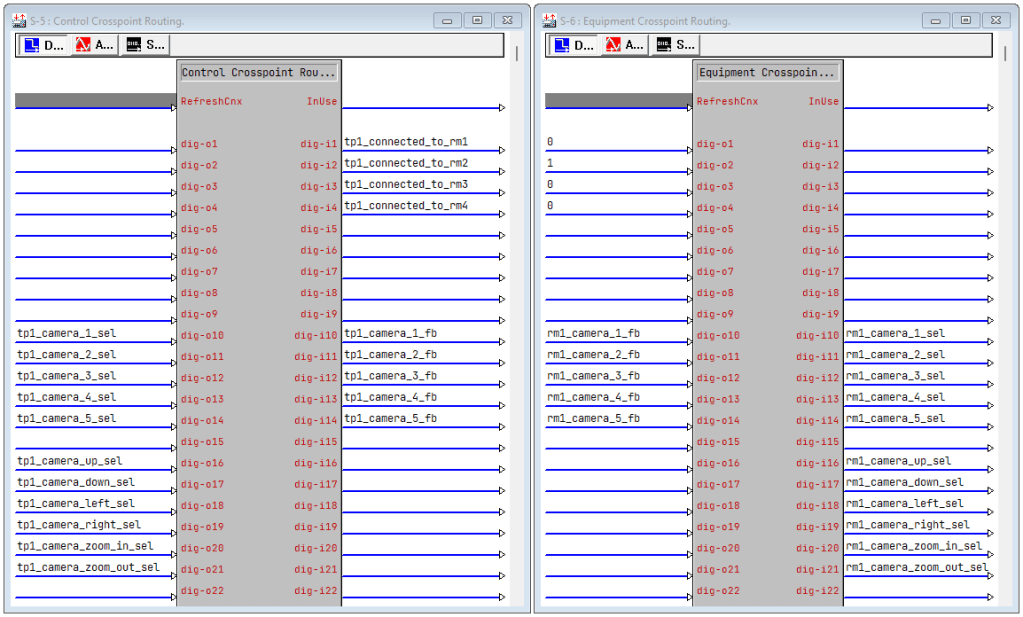
Lets say we’re going to control multiple cameras. We would design our Control Crosspoint to look something like this:

I think of Control Crosspoints as a contract. The devices on the other end should implement as much of the contract as possible since these are the controls that will be available on the touchpanel. In our example, some of our cameras may not have pan/tilt/zoom capabilities, auto-tracking, or whitebalance adjustments. If the selected camera doesn’t have these features, the corresponding joins will be low (so we can disable those buttons on the touchpanel).
We also have to give our Control Crosspoint an ID (the parameter at the bottom). I tend to use 1 for the first touchpanel, 2 for the second, and so on. If I’m breaking things up into logical groups, I might use 1xx for everything that connects to touchpanel 1. For example, if cameras are in control group 3, I might use control ID 103 on the above crosspoint.
Equipment Crosspoints
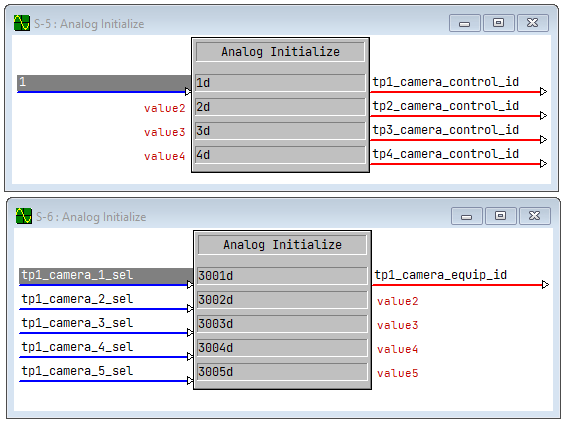
On the other end of the connection, we have the Equipment Crosspoint. This will have the joins that we connect to the device to control it:

What’s with the funny 1, 0, 1 on the left side of our crosspoint though? Remember how a Buffer works when enable goes high? Those signals will propagate through our crosspoint and come out the other side as tp1_camera_has_ptz_fb, tp1_camera_has_auto_fb, and tp1_camera_has_whitebalance_fb, respectively. We’re specifying configuration using our crosspoint, saying this camera has PTZ and whitebalance controls, but doesn’t do auto-tracking.
As for numbering equipment IDs, I usually just pick something higher than any of my control IDs. But if we’re doing logical groups, I might try to pick something like 3xxx, so the first camera would end up being 3001.
You can also use the same IDs as your Control Crosspoints, but that might get confusing.
Crosspoint Connect
Now that we have both ends of the crosspoint added to our program, how do we link the two? For that we use an Equipment/Control Crosspoint Connect symbol:

We pass in the control and equipment IDs then there are a few operations we can perform. This is a special symbol that talks to the crosspoint router engine and makes or breaks ties. Lets look at what each digital join does:
- Connect makes a single connection between ControlID and EquipmentID crosspoint symbols
- DiscEC breaks the single connection between ControlID and EquipmentID crosspoints
- DiscFromC breaks all equipment connections to ControlID
- DiscFromE breaks all control connections to EquipmentID
- DiscAll breaks every crosspoint connection in the program
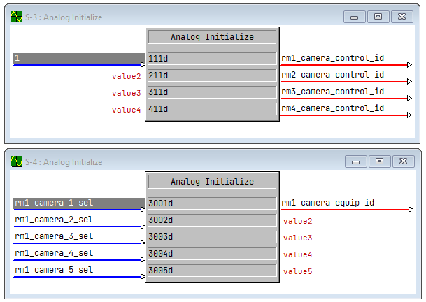
I’ll say the way I have the Equipment/Control Crosspoint Connect symbol wired up is how I use it 99% of the time. Since my control IDs always relate to the same touchpanel, I initialize those at program startup. My equipment IDs will change depending on which camera I select from the touchpanel:
I want to automatically break-then-make crosspoint connections if the equipment ID changes, and I can do that with a Serial/Analog Logic Wave Pulse:
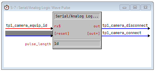
tp1_camera_disconnect will trigger for 1 logic wave and that’s wired to DiscFromC on our Crosspoint Connect symbol. Since our control ID is fixed at program startup, this will disconnect TP1 from all camera crosspoints. In the next logic wave, tp1_camera_disconnect goes low and tp1_camera_connect goes high (in that order). TP1 will then be connected to the new camera identified by tp1_camera_equip_id.
In this fashion, our Control Crosspoint will only ever be connected to one Equipment Crosspoint. We can connect/disconnect our crosspoints for TP1 and not affect TP2, TP3, etc. since they use different control IDs.
I wouldn’t want to simultaneously connect to multiple Equipment Crosspoints from the same Control Crosspoint either because the way signals jam together means the order that crosspoints connect in matters.
Don’t Hide Your Crosspoint Routing
Working with crosspoints does change your thinking a little. It makes me look at the touchpanel joins more as a template rather than what directly controls a device. It means debugging a program requires you to follow a signal through the crosspoint ether to see where it goes.
For that reason, I like to make it obvious that crosspoints are being used. Under my Logic folder, I’ll usually put a Panels folder (for Control Crosspoints) and a Rooms or Devices folder (for Equipment Crosspoints). Or I might label the folder Crosspoints if it’s something weird that doesn’t partition nicely. In either case, I’m trying to make it obvious that there’s a separation between control and equipment.
Never hide crosspoint routing in modules! You’ll lose your sanity trying to trace signal flow in debugger and end up having to crack open modules to fix something stupid like the control side of the crosspoint joins are off by 1.
Don’t Chain Crosspoints
Lets go back to the example of a 4-way divisible space controlling 5 different cameras with different features. Say that we want our touchpanels to track each other when spaces are combined. No problem! We create control IDs and equipment IDs to tie touchpanels to room logic like so:
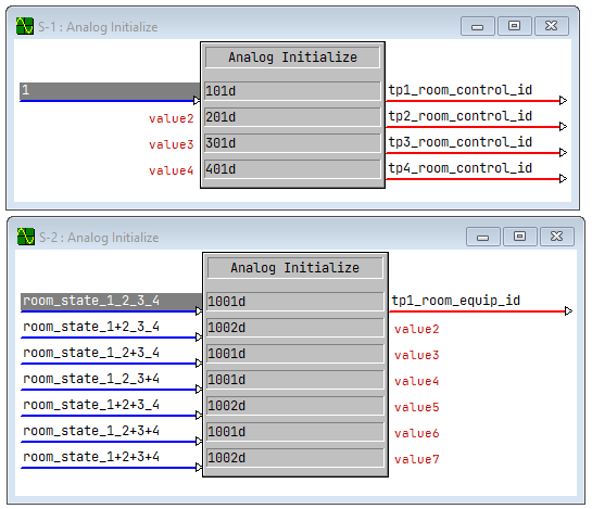
Here we’re saying that all the possible room combinations (seven of them!) we call out exactly which room TP1 should be tied to. Our logic says whichever is the middlemost room is the master, and in the case of 1+2+3+4, room 2 wins.
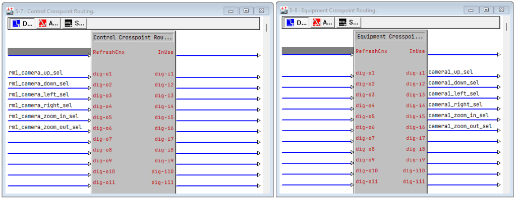
You might be tempted (for the sake of tracking touchpanels 1-to-1) to put the camera selection logic behind the room logic. So you might have something like this for each room:
The camera selection and controls pass through the room crosspoint logic…
…and into the device control logic:
All touchpanels connected to the same room will show the same camera selection feedback and controls. It sounds like what you want, but I would still argue against doing this. Never go past 1 layer of crosspoints or you’re going to spend extra time chasing them around in debugger later.
The way I would write this would be to leave the camera selection as part of the room logic. That way all panels connected to the same room would show the same camera selected. But I’d use the Control Crosspoint feedback to drive the connection from touchpanel to camera directly. Something like this:
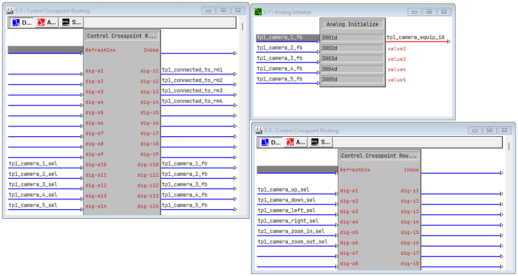
This keeps the crosspoint routing depth to 1, so I can still wrap my brain around it when watching debugger.
Don’t Use Crosspoints For Templated Code
I haven’t run into this in a while now, but I used to see the occasional program that was very templated and would define every join on a touchpanel, typically using something horrific like:
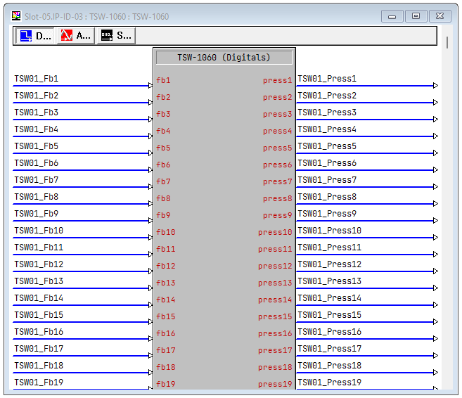
It would then map crosspoints to various things sprinkled throughout the program. TSW01_Press10 may go to several different crosspoint routes and drive very different things across the program when it comes out the other side.
Don’t do this! If you want to write configuration-based systems, use SIMPL#. There’s no way any programmer coming after you will be able to follow the spaghetti of TSW01_Presses.
The Final Word
Crosspoints are just another tool in your toolbelt, and you should use them whenever they make your job easier. I tend to reach for them when programming divisible rooms, but sometimes if things are simple enough, a couple buffers might be all I need. I showed you how I use them 99% of the time, but there is that 1 time out of a 100 where I use them backwards instead.
If you’re looking at a running system and you need to see which crosspoints are currently routed, you can use the ROUTESYMSTAT command:
RMC3>ROUTESYMSTAT
C:[101, S-3] -> E[1001, S-4]
E:[1001, S-4] -> C[101, S-3]
Just got my certification recently and I’ve been poring over your blog to solidify some things I haven’t used in awhile (crosspoints was one of them) and learn some things I haven’t seen yet. Just wanted to say thank you for posting all of this knowledge and insight. This site is a real gem in a very niche industry.
I’m eager to pick up C# and get the silver cert as soon as I can. Good luck with your gold exam.
LikeLiked by 1 person
Congratulations on getting your certification! And thank you for the kind words. I’m just about ready to re-submit my Gold exam (didn’t get a pass on the first submittal). In hindsight, going full C# would have some nice advantages, but I tried to keep the main program in SIMPL. And honestly, I was scared to attempt the whole thing in just C# since I’m still learning the language.
See you at the next Crestron Masters!
LikeLike
I’ve come across a few examples of your ‘Don’t Use Crosspoints For Templated Code’ and have been deathly afraid of wrapping my head around this. Your blog post did a really good job of breaking it down. I too had a very similar class experience as you, where crosspoints were very briefly glanced over. I’m just starting a new project that has more time scheduled than I need (this never happens!) and it’s a rather simple two-way divisible room. Going to give it a try, and hopefully not be terrified over crosspoints after this.
Just wanted to say thank you, from a random internet passerby.
LikeLiked by 1 person
Good luck, John-Paul! I highly recommend giving it a shot. I’ve had programs where crosspoints made it easier to keep the program logic straightforward, so they are useful. But yeah, some programs I’ve opened must have had a separate document describing how it worked because no way could anyone follow the SIMPL logic alone. Which calls up my mantra of “Change As Little As Possible”… 😀
LikeLike