I want to write a few posts about programming AMX NetLinx controllers. While I started my career programming AMX systems, I’m lucky now if I see 1 or 2 in a year. Strangely, every time I’ve started with (or returned to) a company, I’ve been handed a NetLinx system to figure out. It’s sort of a welcoming return to AV because programming in the NetLinx language is well-suited to automation tasks and something about it brings me joy.
Posts in this series:
- NetLinx: Getting Started
- NetLinx: Your First Program
- NetLinx: Testing
- NetLinx: SNAPI
- NetLinx: Modules
- NetLinx: A Real Program
NetLinx Studio
As far as I can tell, NetLinx Studio is available for anyone to download. The current release is v4.4.1914 (released Oct 18 2019):

When you first open NetLinx Studio, the default color scheme is kind of ugly:

If you go to the Settings > Preferences menu, you can select Editor – Highlighting and Fonts to tweak the settings. I prefer using a Solarized Dark color scheme since it’s easier to stare at for long coding sessions. If you want to match my preferences exactly, you can go to the Tools > Import Preferences menu and import my ns4-kiel.epx backup. You can also export your own preferences and save them somewhere in case you ever need to restore them later.

That looks better!
Workspaces
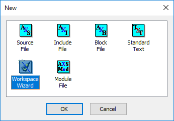
NetLinx likes to bundle projects into workspaces. They’re comparable to SMW files in Crestron’s world. Go to the File > New menu and select Workspace Wizard from the list:
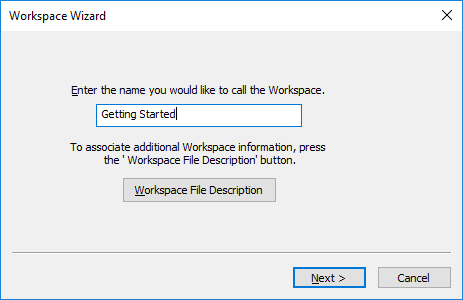
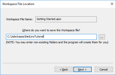
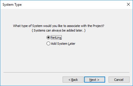
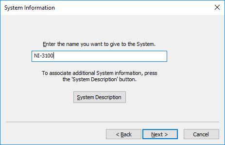
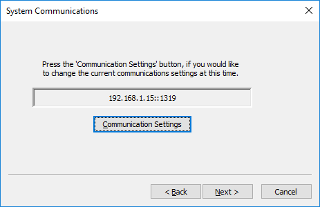
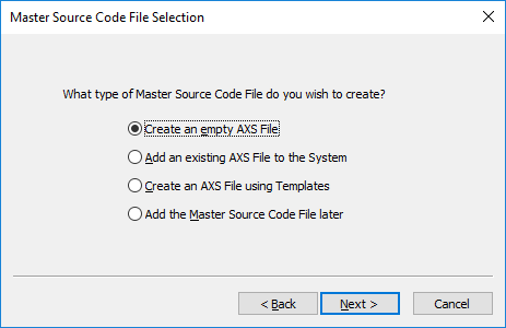
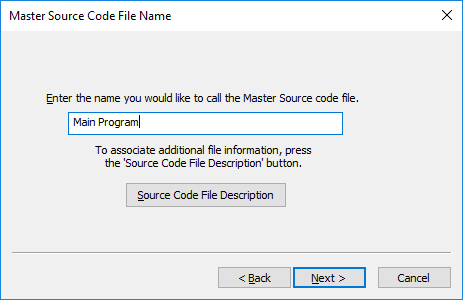
The wizard will walk you through many steps to get everything setup exactly the way you want. You can use the same values as my project or make up your own:


After you click Finish, you’ll see your Main Program file open. The dock shows how your answers in the wizard fill out the workspace tree:


Also note that Main Program has an icon with an M next to it. This means that it is the master program where execution starts when it is loaded to a controller.
Only one source file can be designated master within a system, but later on we’ll explore modules and include files that let you break up your program into bite-sized chunks.
The NetLinx Language
NetLinx is the name of the AMX control platform, but it is also the name of the language used to program it. It’s a mix of programming languages, but is pretty easy to get comfortable with once you learn the structure.
I opted to create a blank NetLinx program during the wizard, so my program consists of:
PROGRAM_NAME='Main Program'
Go to the Edit > Insert Section > DEFINE_DEVICE menu and code will automatically be added to your program:
PROGRAM_NAME='Main Program'
(***********************************************************)
(*          DEVICE NUMBER DEFINITIONS GO BELOW             *)
(***********************************************************)
DEFINE_DEVICE
You don’t have to add sections this way. We could have just typed DEFINE_DEVICE and started adding devices after it. The code snippet also adds a helpful comment that explains what the section is for.
We’re going to add a device definition for the I/O port in our system. You’ll need to look up which port numbers correspond to your controller. It can be difficult to track down information on AMX’s website now, but the hardware reference guide for the NI-3100 has the answer. We’ll use port 17 for the general I/O:
PROGRAM_NAME='Main Program'
(***********************************************************)
(*          DEVICE NUMBER DEFINITIONS GO BELOW             *)
(***********************************************************)
DEFINE_DEVICE

dvIO = 5001:17:0	// GPIO
Devices in NetLinx are specified in D:P:S format (Device:Port:System). In this case, I want to address port 17 (the GPIO) on device 5001 (the integrated controller) in the current system (zero always points to this system whereas you could point to devices located in other systems).
I also want to create a timeline, but lets define a constant to refer to it. Go to the Edit > Insert Section > DEFINE_CONSTANT menu to add this:
PROGRAM_NAME='Main Program'
(***********************************************************)
(*          DEVICE NUMBER DEFINITIONS GO BELOW             *)
(***********************************************************)
DEFINE_DEVICE

dvIO = 5001:17:0	// GPIO

(***********************************************************)
(*               CONSTANT DEFINITIONS GO BELOW             *)
(***********************************************************)
DEFINE_CONSTANT

TL_LOOP = 1
We also need to specify times for our timeline, so go to Edit > Insert Section > DEFINE_VARIABLE to add another section with:
PROGRAM_NAME='Main Program'
(***********************************************************)
(*          DEVICE NUMBER DEFINITIONS GO BELOW             *)
(***********************************************************)
DEFINE_DEVICE

dvIO = 5001:17:0	// GPIO

(***********************************************************)
(*               CONSTANT DEFINITIONS GO BELOW             *)
(***********************************************************)
DEFINE_CONSTANT

TL_LOOP = 1

(***********************************************************)
(*               VARIABLE DEFINITIONS GO BELOW             *)
(***********************************************************)
DEFINE_VARIABLE

LONG lLoopTimes[] = { 500, 500, 500, 500, 500, 500, 500, 500 }
We’ve created an array of times for our timeline. We’ll call into our timeline event 8 times every 500ms.
Now add another section using Edit > Insert Section > DEFINE_START and we’ll create our timeline:
PROGRAM_NAME='Main Program'
(***********************************************************)
(*          DEVICE NUMBER DEFINITIONS GO BELOW             *)
(***********************************************************)
DEFINE_DEVICE

dvIO = 5001:17:0	// GPIO

(***********************************************************)
(*               CONSTANT DEFINITIONS GO BELOW             *)
(***********************************************************)
DEFINE_CONSTANT

TL_LOOP = 1

(***********************************************************)
(*               VARIABLE DEFINITIONS GO BELOW             *)
(***********************************************************)
DEFINE_VARIABLE

LONG lLoopTimes[] = { 500, 500, 500, 500, 500, 500, 500, 500 }

(***********************************************************)
(*                 STARTUP CODE GOES BELOW                 *)
(***********************************************************)
DEFINE_START

TIMELINE_CREATE(TL_LOOP, lLoopTimes, LENGTH_ARRAY(lLoopTimes),
    TIMELINE_RELATIVE, TIMELINE_REPEAT);
The TIMELINE_RELATIVE constant means the timeline will interpret our lLoopTimes array as times relative to the last event fired. So the first one will fire 500ms after the timeline is created, the next will fire 500ms after the 1st event happens, the next will fire 500ms after the 2nd event happens, and so on until we reach the end of our lLoopTimes array. TIMELINE_REPEAT means that once we hit the end of our array, we should start over at the beginning and the process happens forever (until we pause or kill the timeline).
And lastly, we need an event handler for when our timeline fires. Go to Edit > Insert Section > DEFINE_EVENT and add a TIMELINE_EVENT handler:
PROGRAM_NAME='Main Program'
(***********************************************************)
(*          DEVICE NUMBER DEFINITIONS GO BELOW             *)
(***********************************************************)
DEFINE_DEVICE

dvIO = 5001:17:0	// GPIO

(***********************************************************)
(*               CONSTANT DEFINITIONS GO BELOW             *)
(***********************************************************)
DEFINE_CONSTANT

TL_LOOP = 1

(***********************************************************)
(*               VARIABLE DEFINITIONS GO BELOW             *)
(***********************************************************)
DEFINE_VARIABLE

LONG lLoopTimes[] = { 500, 500, 500, 500, 500, 500, 500, 500 }

(***********************************************************)
(*                 STARTUP CODE GOES BELOW                 *)
(***********************************************************)
DEFINE_START

TIMELINE_CREATE(TL_LOOP, lLoopTimes, LENGTH_ARRAY(lLoopTimes),
    TIMELINE_RELATIVE, TIMELINE_REPEAT);

(***********************************************************)
(*                  THE EVENTS GO BELOW                    *)
(***********************************************************)
DEFINE_EVENT

TIMELINE_EVENT[TL_LOOP]
{
    [dvIO,1] = (TIMELINE.SEQUENCE == 1)
    [dvIO,2] = (TIMELINE.SEQUENCE == 2)
    [dvIO,3] = (TIMELINE.SEQUENCE == 3)
    [dvIO,4] = (TIMELINE.SEQUENCE == 4)
    [dvIO,5] = (TIMELINE.SEQUENCE == 5)
    [dvIO,6] = (TIMELINE.SEQUENCE == 6)
    [dvIO,7] = (TIMELINE.SEQUENCE == 7)
    [dvIO,8] = (TIMELINE.SEQUENCE == 8)
}
It’s OK if this code doesn’t make any sense to you at this point! We’re going to dive more into the language itself in the next post, this is just to give us something to test building and loading to a controller. What happens in this event handler is we compare the TIMELINE.SEQUENCE number to see which I/O channel should be active. We test the number against 1 to 8 and assign either TRUE (1) or FALSE (0) to each I/O channel. This results in a chaser pattern where each LED stays lit for half a second:
Compiling to Token Files
Now that we’ve typed in our program, we can build it!
To make sure that you are sending the uncompiled source along with your program, there is a setting you need to check in Settings > Preferences > NetLinx Compiler:

Go to the Build > Build Workspace menu and you’ll see the NetLinx compiler try to build your program. You should see results like this in the Status window:
---------- Starting NetLinx Compile - Version[2.5.2.420] [06-08-2021 10:16:31] ----------
C:\Jobs\repos\NetLinxTutorial\Main Program.axs
C:\Jobs\repos\NetLinxTutorial\Main Program.axs - 0 error(s), 0 warning(s)
Compiled Code takes 14905 bytes of memory -- Token and Variable Count is 815 (Maximum is 200000)

Compressing Source Code Files...
Created SRC file: C:\Jobs\repos\NetLinxTutorial\Main Program.src
NetLinx Compile Complete [06-08-2021 10:16:32]

>>>>--- NetLinx Compiles:  1 Files  0 Total Error(s)  0 Total Warnings(s) ---<<<<
This will compile our program down to a token (TKN) file and this is what gets loaded to the controller. If our project contained other NetLinx or Java modules, those would get loaded to our controller as well.
File Transfer
If everything built with zero errors, then we’re ready to load the token file to our controller. Go to the Tools > File Transfer menu to open the file transfer window. Select the Add button and put a checkmark next to the system you want to load. All the necessary files from the workspace will be sent:

Sending the program actually sends two files: the compiled TKN file and a zipped SRC archive of the uncompiled program. This can save you down the road if you ever need to recover a lost program from a controller! Hit Send to send both to your controller.

After the program is sent, the controller will reboot and about a minute later you’ll see the program running.
Next Time
In the next part we’ll dive deeper into the NetLinx language and create something with a touchpanel layout. I’ll walk through the language constructs a bit better, but at least we got the basics out of the way:
- We can create new workspaces
- Build programs (with source included!)
- Load to a controller
Thanks for reading!

Thanks for your time ! this helps starting with amx at some easy step 🙂
LikeLiked by 1 person