In this post, we’ll explore the Standard NetLinx API–or SNAPI, for short. This is one of those topics I didn’t fully embrace when I started programming AMX, but over time, I grew to appreciate the benefits of adhering to a standard.
I’ve updated the touchpanel layout in this post, so if you want to grab the latest code, it’s available on GitHub.
Other posts in this series:
- NetLinx: Getting Started
- NetLinx: Your First Program
- NetLinx: Testing
- NetLinx: SNAPI
- NetLinx: Modules
- NetLinx: A Real Program
What is an API?
API stands for Application Programming Interface. It’s a contract used to call out to other functions, libraries, or services from your code. Every API might be different; there is typically a specification that shows you how to program for it. SNAPI is a specification for AMX modules, and we’ll explore how using it can also make your code easier to read and update. Always a benefit to have for future programmers who have to touch your program (especially if you are also that future programmer).
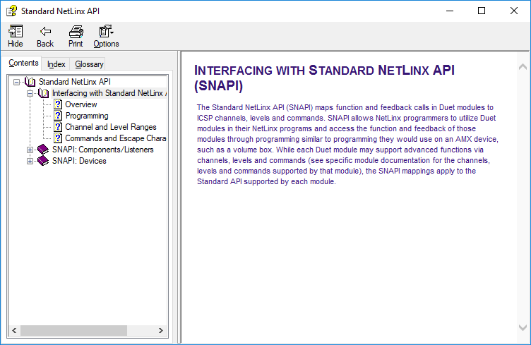
Luckily, finding the SNAPI documentation is easy! Go to Help > Standard NetLinx API Help in NetLinx Studio to open it. If you browse through it a bit, you can see how it’s structured to provide access to Duet modules (which are written in Java) to NetLinx programs.
Touchpanel Updates
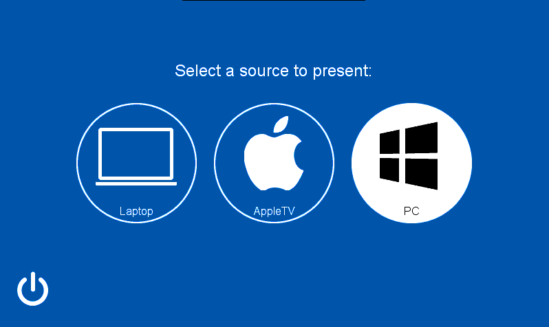
I want to use our touchpanel layout to demonstrate the power of sticking with a standard, but we need to add a little more plumbing before we get there. First, I want to update our source selection page with another button:
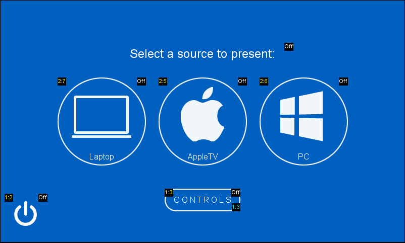
If we load this layout to our touchpanel, the CONTROLS button isn’t there! That’s because I’ve set the visibility to hidden by default. I really only want it to appear if AppleTV is the selected source. Let’s add some code to handle the source selection feedback:
DEFINE_VARIABLE

LONG lLoopTimes[] = { 500, 500, 500, 500, 500, 500, 500, 500 }

INTEGER btnSystemPower[] = { 1, 2 }
INTEGER btnSources[]     = { 1, 2, 3, 4, 5, 6, 7, 8 }
Wait a second. How can we have overlap between btnSystemPower and btnSources? They both have channels 1 and 2 in them!
If you look at the Source Selection popup above, you’ll notice the source buttons are defined on port 2 and the power button is on port 1 (the yellow text overlaid on each button). We need to create another device in our program to represent this second port:
DEFINE_DEVICE

dvCONSOLE = 0:1:0	    // Master Controller

dvCOM1 = 5001:1:0	    // RS-232 port 1
dvCOM2 = 5001:2:0	    // RS-232 port 2

dvIR1 = 5001:9:0	    // IR port 1
dvIR2 = 5001:10:0	    // IR port 2

dvRELAY = 5001:8:0	    // Relays
dvIO    = 5001:17:0	    // GPIO

dvTP1     = 10001:1:0	// MXP-9000i
dvTP1_SWT = 10001:2:0	// Switcher controls

vdvROOM = 33001:1:0
We can use dvTP1_SWT to refer to the buttons in our layout that control an AV switcher. I plan to use the channel number of those buttons to map to the actual input on the switcher. That way, if a source needs to move to a different input, I just have to change the channel number on the layout. We’ll write a button event to handle the feedback on the touchpanel:
DEFINE_EVENT

DATA_EVENT[dvTP1]
{
    ONLINE:
    {
	    SEND_COMMAND dvTP1, 'ADBEEP'
    }
}

BUTTON_EVENT[dvTP1,btnSystemPower]
{
    PUSH:
    {
	    TO[BUTTON.INPUT]

    	[vdvROOM,255] = (GET_LAST(btnSystemPower) == 1)
    }
}

BUTTON_EVENT[dvTP1_SWT,btnSources]
{
    PUSH:
    {
	    INTEGER i, n

  	    n = GET_LAST(btnSources)

	    FOR (i = 1; i <= 8; i++)
	    {
	        [dvTP1_SWT,i] = (i == n)
	    }
    }
}

CHANNEL_EVENT[vdvROOM,255]
{
I’ve hard-coded the range of our switcher inputs right into the button event here which isn’t a very good practice. But we’re still building up to our final program, so it’s OK for testing things as they are now. Once you load this program, you’ll be able to “select” different sources:
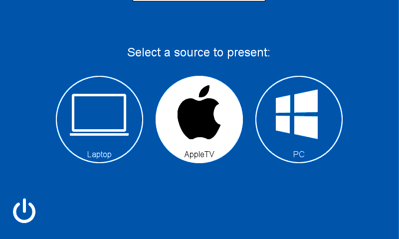
Remember, I want the CONTROLS button to appear if we select AppleTV. Lets modify the button event to check for which source is selected:
BUTTON_EVENT[dvTP1_SWT,btnSources]
{
    PUSH:
    {
	    INTEGER i, n

	    n = GET_LAST(btnSources)

	    FOR (i = 1; i <= 8; i++)
	    {
	        [dvTP1_SWT,i] = (i == n)
	    }

	    IF (n == 5) // AppleTV input
	    {
	        SEND_COMMAND dvTP1,'^SHO-3,1'
	    }
	    ELSE
	    {
	        SEND_COMMAND dvTP1,'^SHO-3,0'
	    }
    }
}
We use the ^SHO command to show or hide the button based on which input was selected. This command works with the address code of the button instead of the channel code. In this screenshot above, that’s the cyan text overlaid on the button in the lower-right corner. Pushes and feedback happen on the channel code, modifying the button itself happens on the address code. Subtle difference.
Now, when we select AppleTV, we can see our new button! And if we select something else, the button disappears:
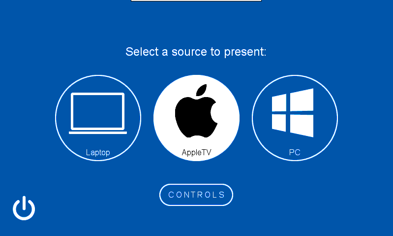
Still, nothing happens when we push the CONTROLS button. Lets add that now:
BUTTON_EVENT[dvTP1,btnSystemPower]
{
    PUSH:
    {
	    TO[BUTTON.INPUT]

    	[vdvROOM,255] = (GET_LAST(btnSystemPower) == 1)
    }
}

BUTTON_EVENT[dvTP1,3]	// Toggle AppleTV popup
{
    PUSH:
    {
	    TO[BUTTON.INPUT]

	    SEND_COMMAND dvTP1,'PPOG-AppleTV'
    }
}

BUTTON_EVENT[dvTP1_SWT,btnSources]
{
The PPOG command can be used to toggle a popup on and off. Now the popup works as expected:
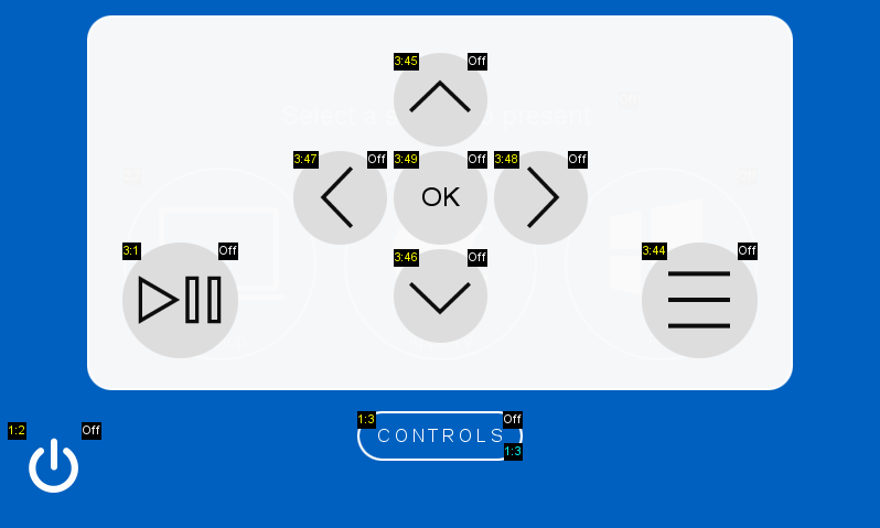
You might have noticed that the buttons on this popup have a new port number: 3. And the channel numbers are spread out a bit: 1, 44, 45, 46, 47, 48, and 49. You might assume these channel numbers are important in SNAPI, and you would be correct. I’ll show you how I got those numbers in just a minute.
Why Have Standards?
Now that we’ve done all of that, we can get back to talking about standard APIs. Here’s a list of why I would choose to follow a standard like SNAPI today versus creating something new on the spot:
- I don’t have to think about how it works, that part is already documented
- I can keep different components of my program consistent
- It will be easier to swap out a component in the future since everything follows the same API
The AppleTV controls are a good example. If we open the IR driver, we can see where the functions were saved:
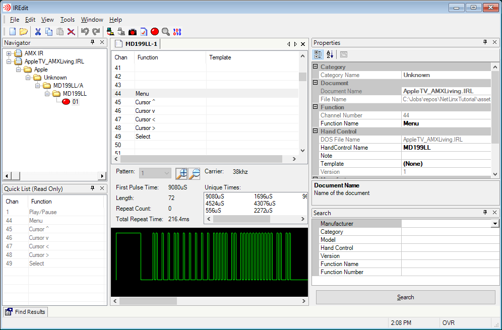
On the left-hand side of the window, you can see the same channel numbers we assigned to the buttons on our touchpanel layout. These are the SNAPI channels for transport deck controls.
Say in the future, we remove the AppleTV from the system and drop a Roku player in instead. AMX has a Duet module we can use to communicate with the new player via TCP/IP. But guess what? We still rely on the same channel numbers to perform the same functions, even though we’re no longer pulsing IR codes, the module turns them into REST API calls. The same SNAPI channel numbers are used in both control methods.
This allows us to make minimal changes to the UI and the code, which means we’re less likely to make a mistake updating something later on. At least for me, any chance to minimize mistakes helps me out greatly.
How SNAPI Works
There’s a diagram included with almost every Duet module that looks like this:
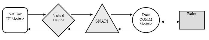
This shows the relationship between our NetLinx code (on the left) and the physical device (all the way on the right). Most of the work in this diagram is being done within the Duet COMM Module to translate our pushes on channel 45 into whichever command tells the Roku to move the cursor up. Those details are hidden from us, and that means we can focus on making sure the User Interface is easy to use.
We don’t have to use Duet modules, or SNAPI, or anything standard if we don’t want to. If we’re worried about which commands are being sent to the Roku player, we can write everything from scratch. But Duet means we don’t have to worry about those details, and SNAPI is the API we use to make sure our logic connects up correctly to the modules we use.
Making Our Code SNAPI
We can get access to SNAPI in our program by including the header file. This is a file saved in a central location NetLinx Studio knows to check, so you don’t have to include the path to it:
(***********************************************************)
(*               CONSTANT DEFINITIONS GO BELOW             *)
(***********************************************************)
DEFINE_CONSTANT

TL_LOOP = 1

(***********************************************************)
(*                  INCLUDE FILES GO BELOW                 *)
(***********************************************************)

#INCLUDE 'SNAPI'

(***********************************************************)
(*               VARIABLE DEFINITIONS GO BELOW             *)
(***********************************************************)
DEFINE_VARIABLE
If you right-click on the #INCLUDE 'SNAPI' line, you can select Open Include File from the pop-up menu. This will open SNAPI.axi in a new document window. If you scroll down a little ways, you can see some of the constants defined in this file:
(***********************************************************)
(*                        Amplifier                        *)
(***********************************************************)
                // Amplifier Channels and Levels

// Amplifier Channels
POWER                  = 9     // Momentary: Cycle power
VOL_UP                 = 24    // Ramping:   Ramp volume up
VOL_UP_FB              = 24    // Feedback:  Volume ramp up feedback
VOL_DN                 = 25    // Ramping:   Ramp volume down
VOL_DN_FB              = 25    // Feedback:  Volume ramp down feedback
VOL_MUTE               = 26    // Momentary: Cycle volume mute
PWR_ON                 = 27    // Momentary: Set power on
PWR_OFF                = 28    // Momentary: Set power off
VOL_PRESET             = 138   // Momentary: Cycle volume preset
VOL_MUTE_ON            = 199   // Discrete:  Set volume mute
VOL_MUTE_FB            = 199   // Feedback:  Volume mute feedback
DEVICE_COMMUNICATING   = 251   // Feedback:  Device online event
DATA_INITIALIZED       = 252   // Feedback:  Data initialized event
POWER_ON               = 255   // Discrete:  Set power
POWER_FB               = 255   // Feedback:  Power feedback

// Amplifier Levels
VOL_LVL                = 1     // Level: Volume level (0-255)
The channels pertain to amplifiers, but many other devices may also have power and volume controls. They’ll all use the same channel numbers.
We can go through our code and change some of the numbers to constants found within this include file. It will help make our code more readable and make sure we follow SNAPI when communicating between devices:
BUTTON_EVENT[dvTP1,btnSystemPower]
{
    PUSH:
    {
	    TO[BUTTON.INPUT]

	    [vdvROOM,POWER_ON] = (GET_LAST(btnSystemPower) == 1)
    }
}
CHANNEL_EVENT[vdvROOM,POWER_FB]
{
    ON:
    {
	    SEND_COMMAND dvTP1,'@PPK-Start System'
	    SEND_COMMAND dvTP1,'@PPN-Source Selection'
    }
    OFF:
    {
	    SEND_COMMAND dvTP1,'@PPK-Source Selection'
	    SEND_COMMAND dvTP1,'@PPN-Start System'
    }
}
CHANNEL_EVENT[dvIO,1]	// Fire Alarm
{
    OFF:
    {
	    OFF[vdvROOM,POWER_ON]
    }
}
If we dig through SNAPI.axi a little more, we can find a section for Digital Media Server (which is kind of what an Apple TV is). We can grab some of the channel constants here to define our transport controls back in the program:
(***********************************************************)
(*               VARIABLE DEFINITIONS GO BELOW             *)
(***********************************************************)
DEFINE_VARIABLE

LONG lLoopTimes[] = { 500, 500, 500, 500, 500, 500, 500, 500 }

INTEGER btnSystemPower[] = { 1, 2 }
INTEGER btnSources[]     = { 1, 2, 3, 4, 5, 6, 7, 8 }

INTEGER btnAppleTV[] = {
	    PLAY,
	    MENU_FUNC,
	    MENU_UP,
	    MENU_DN,
	    MENU_LT,
	    MENU_RT,
	    MENU_SELECT
    }
Remember that we put our deck transport controls on a different port number, so we’ll need to define a new device for it in our program:
DEFINE_DEVICE

dvCONSOLE = 0:1:0	     // Master Controller

dvCOM1 = 5001:1:0	     // RS-232 port 1
dvCOM2 = 5001:2:0 	     // RS-232 port 2

dvIR1 = 5001:9:0	     // IR port 1
dvIR2 = 5001:10:0	     // IR port 2

dvRELAY = 5001:8:0	     // Relays
dvIO    = 5001:17:0	     // GPIO

dvTP1       = 10001:1:0	 // MXP-9000i
dvTP1_SWT   = 10001:2:0	 // Switcher controls
dvTP1_TPORT = 10001:3:0	 // Transport controls

vdvROOM = 33001:1:0
And deeper into our program, we can add a button event to map these channels to our Apple TV (on IR port 1):
}

BUTTON_EVENT[dvTP1_TPORT,btnAppleTV]
{
    PUSH:
    {
	    TO[dvIR1,BUTTON.INPUT.CHANNEL]
    }
}

CHANNEL_EVENT[vdvROOM,POWER_FB]
{
Build this workspace and load to your controller. Now when you touch the AppleTV controls on our pop up, you’ll see IR port 1 flash as commands are sent out.
Next Time
In the next post, we’ll look at cleaning up the UI code a little and writing a module that we can reuse. Thanks for reading!

5 thoughts on “NetLinx: SNAPI”