This post will cover how we can use NetLinx Studio to test our program, especially in the absence of real equipment.
Other posts in this series:
- NetLinx: Getting Started
- NetLinx: Your First Program
- NetLinx: Testing
- NetLinx: SNAPI
- NetLinx: Modules
- NetLinx: A Real Program
Before we get into testing our program, let’s take a minute to go over virtual devices.
Virtual Devices
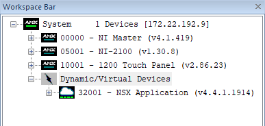
Virtual devices behave exactly like physical devices as far as your program is concerned, but they do have a special numbering. Virtual devices are in the range 32768 to 36863 (0x8000 to 0x8FFF). When you connect to a controller with NetLinx Studio, you can see which virtual devices exist.
Device 32001 is a Dynamic Device representing the NetLinx Studio application. Its number is automatically assigned. Any devices in the range 32001 to 32767 are dynamic.
Virtual devices defined in our program will appear in the same grouping though.
Lets create a virtual device to represent our room:
DEFINE_DEVICE

dvCONSOLE = 0:1:0	// Master Controller

dvCOM1 = 5001:1:0	// RS-232 port 1
dvCOM2 = 5001:2:0	// RS-232 port 2

dvIR1 = 5001:9:0	// IR port 1
dvIR2 = 5001:10:0	// IR port 2

dvRELAY = 5001:8:0	// Relays
dvIO    = 5001:17:0	// GPIO

dvTP1 = 10001:1:0	// NXT-1200

vdvROOM = 33001:1:0
Build the program and send it to the controller. Now when you refresh the Online Tree you’ll see the virtual device listed.
Virtual devices default to having one available port, but we can assign more if we need to. It all depends how you plan to interact with it.

Lets update our button events to control this virtual device.
Button Groups
If you look at our button events, they’re nearly identical. It would be great if we could combine them into one handler, then we only have to look in one place when something related to the system power is affected. We’ll define an array of channel numbers we want to handle in DEFINE_VARIABLE:
DEFINE_VARIABLE

LONG lLoopTimes[] = { 500, 500, 500, 500, 500, 500, 500, 500 }

INTEGER btnSystemPower[] = { 1, 2 }
Now we can rewrite our button event to look like this:
DEFINE_EVENT

DATA_EVENT[dvTP1]
{
    ONLINE:
    {
	    SEND_COMMAND dvTP1, 'ADBEEP'
    }
}

BUTTON_EVENT[dvTP1, btnSystemPower]
{
    PUSH:
    {
	    TO[BUTTON.INPUT]

	    SWITCH (GET_LAST(btnSystemPower))
	    {
	        CASE 1: // Power On
	        {
		        SEND_COMMAND dvTP1,'@PPK-Start System'
		        SEND_COMMAND dvTP1,'@PPN-Source Selection'
	        }
	        CASE 2: // Power Off
	        {
		        SEND_COMMAND dvTP1,'@PPK-Source Selection'
		        SEND_COMMAND dvTP1,'@PPN-Start System'
	        }
	    }
    }
}

TIMELINE_EVENT[TL_LOOP]
{
    [dvIO,1] = (TIMELINE.SEQUENCE == 1)
    [dvIO,2] = (TIMELINE.SEQUENCE == 2)
    [dvIO,3] = (TIMELINE.SEQUENCE == 3)
    [dvIO,4] = (TIMELINE.SEQUENCE == 4)
    [dvIO,5] = (TIMELINE.SEQUENCE == 5)
    [dvIO,6] = (TIMELINE.SEQUENCE == 6)
    [dvIO,7] = (TIMELINE.SEQUENCE == 7)
    [dvIO,8] = (TIMELINE.SEQUENCE == 8)

    IF (TIMELINE.SEQUENCE == 8)
    {
	    SEND_STRING dvCONSOLE, 'One more time!'
    }
}
Any time a channel in btnSystemPower fires an event (in this case, channels 1 or 2), our handler will run. We call GET_LAST to figure out which channel caused the event to fire. GET_LAST returns the index into our array rather than the actual channel number. Very similar to GetLastModifiedArrayIndex in SIMPL+ but doesn’t punish you by typing out the full alphabet.
But what about if we have other events that can trigger the system to power on or off? We want to have similar behavior whether a button press turns the system on or an incoming call does. This is where our virtual device comes in handy.
CHANNEL_EVENT
A channel event is similar to a button event, but only deals with the channel turning on or off. I’m going to pick a specific channel number for now, but it will make more sense once we talk about SNAPI in a future post. Lets add a CHANNEL_EVENT to our program:
DEFINE_EVENT

DATA_EVENT[dvTP1]
{
    ONLINE:
    {
        SEND_COMMAND dvTP1, 'ADBEEP'
    }
}

BUTTON_EVENT[dvTP1, btnSystemPower]
{
    PUSH:
    {
        TO[BUTTON.INPUT]

        SWITCH (GET_LAST(btnSystemPower))
        {
            CASE 1: // Power On
            {
                ON[vdvROOM,255]
            }
            CASE 2: // Power Off
            {
                OFF[vdvROOM,255]
            }
        }
    }
}

CHANNEL_EVENT[vdvROOM,255]
{
    ON:
    {
	    SEND_COMMAND dvTP1,'@PPK-Start System'
	    SEND_COMMAND dvTP1,'@PPN-Source Selection'
    }
    OFF:
    {
	    SEND_COMMAND dvTP1,'@PPK-Source Selection'
	    SEND_COMMAND dvTP1,'@PPN-Start System'
    }
}

TIMELINE_EVENT[TL_LOOP]
{
    [dvIO,1] = (TIMELINE.SEQUENCE == 1)
    [dvIO,2] = (TIMELINE.SEQUENCE == 2)
    [dvIO,3] = (TIMELINE.SEQUENCE == 3)
    [dvIO,4] = (TIMELINE.SEQUENCE == 4)
    [dvIO,5] = (TIMELINE.SEQUENCE == 5)
    [dvIO,6] = (TIMELINE.SEQUENCE == 6)
    [dvIO,7] = (TIMELINE.SEQUENCE == 7)
    [dvIO,8] = (TIMELINE.SEQUENCE == 8)

    IF (TIMELINE.SEQUENCE == 8)
    {
	    SEND_STRING dvCONSOLE, 'One more time!'
    }
}
We’ve moved the touchpanel logic to our CHANNEL_EVENT and now the BUTTON_EVENT just has to worry about turning channels on or off. We can simplify the button event handler further by rewriting it like this:
BUTTON_EVENT[dvTP1, btnSystemPower]
{
    PUSH:
    {
        TO[BUTTON.INPUT]

        [vdvROOM,255] = (GET_LAST(btnSystemPower) == 1)
    }
}
If the expression evaluates TRUE, channel 255 is set to ON, otherwise, it is OFF.
Emulating a Device
Lets pretend that we have a fire safety system that should also shutdown the room if the alarm triggers. This trigger will be normally closed (NC) so we should monitor when the I/O channel opens (goes OFF) in our program. Lets also get rid of the chaser pattern we were animating on the I/O channels:
DEFINE_EVENT

DATA_EVENT[dvTP1]
{
    ONLINE:
    {
        SEND_COMMAND dvTP1, 'ADBEEP'
    }
}

BUTTON_EVENT[dvTP1, btnSystemPower]
{
    PUSH:
    {
        TO[BUTTON.INPUT]

        [vdvROOM,255] = (GET_LAST(btnSystemPower) == 1)
    }
}

CHANNEL_EVENT[vdvROOM,255]
{
    ON:
    {
        SEND_COMMAND dvTP1,'@PPK-Start System'
        SEND_COMMAND dvTP1,'@PPN-Source Selection'
    }
    OFF:
    {
        SEND_COMMAND dvTP1,'@PPK-Source Selection'
        SEND_COMMAND dvTP1,'@PPN-Start System'
    }
}

CHANNEL_EVENT[dvIO,1]	// Fire Alarm
{
    OFF:
    {
        OFF[vdvROOM,255]
    }
}
If the fire alarm trigger goes low, we shut the room down. If it goes high again, we don’t do anything. Build this program and send it to your controller.
To watch the communication between devices, we need to go to Diagnostics > NetLinx Device Notification Options. Double-click on the All Devices line and make sure it matches this:
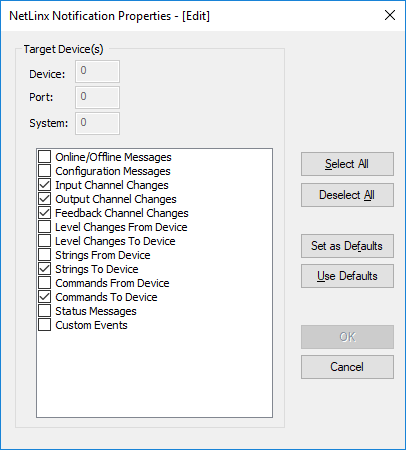
Click Done. If there are any messages in the Notifications window, you can right-click and select Clear.

Turn the system on using the touchpanel. You’ll see it flip to the source selection page.
If you press the Power button in the lower corner, it shuts the system off and returns to the start page.
Make sure you leave the panel on the source selection page.
Now lets test to see if the system shuts down when the fire alarm triggers. Go to Diagnostics > Emulate a Device. You’ll need to enter the device number, port, and system that you’re pretending to be. Remember that port numbers might change depending on which controller you’re using. It should match what is in the program:
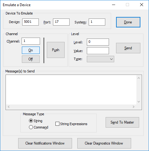
Where it says Channel, enter 1 since that’s where we’ll connect the fire safety relay. Hit Off. Nothing happens! Our channel was probably already off, and our event handler only triggers if we go from ON to OFF. Hit On and then hit Off. You’ll see in the Notifications window:
Line      1 2021-06-16 (16:23:14):: Output Channel:On [5001:17:1] - Channel 1
Line      2 2021-06-16 (16:23:15):: Output Channel:Off [5001:17:1] - Channel 1
Line      3 2021-06-16 (16:23:15):: Feedback:Off [33001:1:1] - Channel 255
Line      4 2021-06-16 (16:23:15):: Output Channel:Off - From [33001:1:1] - Channel 255
The touchpanel should be back on the Touch to Start Screen page. We’ll improve this UI in a future post, but it’s fine for now.

Using NetLinx Studio and Emulate a Device, we were able to test our fire alarm logic without having to actually wire up a test circuit to the GPIO port on our controller.
Next Time
In the next post, we’ll look at SNAPI, the Standard NetLinx API. It defines a standard for channels so we can abstract away the actual device we’re controlling.
See you then!

5 thoughts on “NetLinx: Testing”